Intro:
Creating interrupt service routines using assembly isn't as hard as people think. With the exception of the initial setup it is really no different than writing any other code and has the added benefit of allowing the processor to work on it's main task instead of, for example, waiting around to send/receive the next character over the serial interface. There is a little setup to get the processor to execute an interrupt routine, but once you understand how they work it's actually quite simple.
The Code
The code is written for an ATMega328, the same chip used on the current Arduino Uno. The code is compiled using avra assembler and loaded to an Uno using avrdude. Once the code is loaded, open the serial monitor from the Arduino IDE and try it out.
;
;serialint.asm
;
;USART implementation using interrupts.
;

.device atmega328p

.equ UDR0 = 0xc6      ;USART Data Register
.equ UBRR0L = 0xc4    ;USART Baud Rate Register Low
.equ UBRR0H = 0xc5    ;USART Baud Rate Register High
.equ UCSR0A = 0xc0    ;USART Control and Status Register A
.equ UCSR0B = 0xc1    ;USART Control and Status Register B
.equ UCSR0C = 0xc2    ;USART Control and Status Register C
.equ UDRE0 = 5

;Again, interrupt vectors for the 328p are different than
;48 or 88 device. This is the second time this has bitten me.

;Reset Vector
.org 0x0000
  jmp Main

;USART Receive Interrupt Vector
.org 0x0024
  jmp Rx_ISR

;USART Transmit Interrupt Vector
.org 0x0028
  jmp Tx_ISR

.org 0x0040
Main:
  ;Disable interrupts while doing setup
  cli

  ;Set up USART
  call SerialInit

  ;Allow interrupts
  sei

  ;Point Z-Register to our message and send.
  ;Address of message is shifted left one bit since data in
  ;program space is stored 16-bits wide. The LSB of the Z
  ;register is used to distinguish between the upper or lower
  ;byte.
  ldi r30, low(message<<1)
  ldi r31, high(message<<1)
  call TxEnable

;Wait here until the end of time.
loop:
  rjmp loop

;
;SerialInit - Initialize the USART
;
SerialInit:
  ;Set BAUD rate to 9600 (assuming a 16MHz system clock)
  clr r17
  sts UBRR0H, r17
  ldi r16, 0x67
  sts UBRR0L, r16

  ;Enable transmitter and receiver.
  ;Enable interrupts for USART Receive.
  ldi r16, 0x98
  sts UCSR0B, r16

  ;Not going to do anything with UCSR0C since the default
  ;values will give the 8:N:1 format needed to communicate
  ;with the serial monitor of the Arduino IDE.

  ret

TxEnable:
  ;Enable the transmit interrupt allowing the ISR to
  ;push the string out over the serial interface.
  push r17
  lds r17,UCSR0B
  ori r17,0x40
  sts UCSR0B, r17

  ;Send first character. Interrupt routine will take
  ;care of the rest.
  lpm r17, Z+
  sts UDR0,r17

  pop r17

  ret

;
;Rx_ISR - Interrupt routine to deal with any incoming data
;
Rx_ISR:
  ;Read the data register, and send it back.
  lds r16,UDR0
  sts UDR0, r16

  reti

;
;Tx_ISR - Interrupt routine to load next byte to send
;
Tx_ISR:
  push r17

  lpm r17,Z+
  tst r17
  breq Tx_Done
  sts UDR0,r17
  pop r17
  reti
Tx_Done:
  ;Turn off transmit interrupts.
  lds r17, UCSR0B
  andi r17, 0xBF
  sts UCSR0B, r17

  pop r17

  reti

;Program data
message: .db "Using USART with interrupts.",0x0c,0x0a,0x00
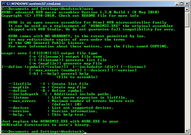
Save the code to a file called serialint.asm. To assemble, open a terminal window,
change to the directory of the file and issue the command:
avra serialint.asm
Once compiled, transfer the hex file using avrdude with the following command:
avrdude -patmega328p -carduino -P/dev/ttyACM0 -b115200
            -Uflash:w:"serialint.hex":i
The serial port on my system is ttyACM0, yours may be different.
Now open the Arduino IDE and go to the Serial Monitor. As long as it's set for 9600 baud you should see the following...
The interrupt vector table begins at location 0x0000, which is the RESET vector. The main program starts at location 0x0040 which is the next location after the interrupt vector table. A complete list of vectors can be found in the atmega328p datasheet. Just insert a jump instruction to your service routine and enable the particular interrupt to use it. You will also need to enable the global interrupt flag. Don't forget that. None of the interrupts will execute without it.


